The overdriven sound of a valve power amplifier is highly desirable,
with many different output stage designs to produce the variety of
trademark sounds heard on modern recordings.
The only problem is that a valve power amplifier is only capable of
producing this sound at one volume (usually, fairly loud!).
Dummy speaker loads (the good ones are not just resistive, they need
to simulate the reactive load of a speaker) allow a player to use one
amplifier in a variety of playing situations and styles by running the
amplifier at the desired level, and using the dummy load to regulate the
volume level.
Another option for the playing musician is to use a variety of
amplifiers, however, this approach appeals only to rare wealthy
musicians.

There are probably 3 distinctly identifiable types of valve power amplifiers used:
-
Leo Fender's classic early designs used 6V6 tubes, and later, the
higher powered 6L6's.
This gave a characteristic full and punchy sound, suitable for many
styles of the day, and later.
Steel and country players like the chime-like clean sounds, and
blues players were quick to discover the classic way it breaks up when
pushed hard.
At really high overdrive, though, the sound becomes quite dirty,
with bass in particular sounding flabby.
-
Marshall designs started as Fender copies, but soon switched to EL34 output tubes, possibly for local supply reasons.
Anyway, the rest is history.
These tubes exhibit a softer overdrive transition, and maintain clarity even at high overdrive levels.
They also have a limited middle response, giving rise to the famous Marshall crunch sound.
The lower powered EL84 tubes have similar characteristics.
-
Vox AC30 (and the more popular top boost model) uses a Class AB
power amplifier design, with the valves biased "hot", so while this
operates in class A at lower levels, it is really a class AB design.
There's no negative feedback in the power amp either, so this gives a
different sound, often described as a sweeter overdrive.
Listen to Brian May's sounds for plenty of good examples.
The Fender and Marshall designs use class AB for their output designs,
biased with the valves almost off with no signal.
This is more efficient (more watts per tube), and better for tube
life.
When you play, tubes take turns handling each half of the signal.
This leads to some minor distortion as the tubes cross over which is
all but eliminated with the negative feedback.
Class A designs are rare in medium to high power guitar amps, but true
class A has the tubes operating at half power with no signal applied.
When you play, the tube fluctuates between full and no power, so there
is no switching to add unwanted distortion.
This is a very superficial explanation; please read elsewhere on the
Internet for more detailed descriptions.
Boutique amplifier builders offer composite designs, offering
characteristics of all designs.
This can be done dynamically (by responding to picking strength and
volume settings), or with various switching schemes.
Mesa Boogie has built it excellent reputation for tube preamp
overdrive and tone shaping designs, used in conjunction with high
quality tube power amplifiers.
For most of us, we can use a wide range of effective stomp boxes for
our overdrive and distortion sounds.
There is much history on the attempts to recreate the desirable
overdrive sounds with various non-linear preamplifier designs.
When a player tests one of these devices, the first impression is
usually formed on the type of overdrive character and tone produced, and
players will be looking for sufficient flexibility in the controls to
tailor this to their personal tastes.
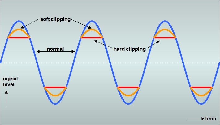
The basic types of overdrive are generally classified as soft and hard
clipping.
Soft Clipping
This is usually marketed as "overdrive", where the gain is inversely
proportional to the input signal level.
This is typically produced either with back to back silicon signal
diodes in the negative feedback path of an op-amp, or with germanium
diodes or LEDs back to back in a shunt to ground.
Hard Clipping
Usually marketed as "distortion", where the signal level is restricted within a range.
This is typically produced with silicon diodes back to back in a shunt to ground.
This is the same as the circuit above, using silicon instead of germanium/LED diodes.
Here's a picture of what soft and hard clipping do to your guitar signal:
There are some other criteria which players will notice (not necessarily immediately) when using these designs:
The ability to retain timbre
Different guitar pickup combinations produce recognisable signature
sounds of the instrument used.
By its nature, overdrive will mask this timbre to some extent,
however, many musical styles prefer to retain as much of the original
character as possible.
Inter-modulation distortion
Again, by its nature, overdrive will produce inter-modulation
distortion when two or more notes are played together.
For just two notes played, inter-modulation distortion produces an
additional note with a frequency of the difference between the original
two notes.
For chords, where up to 6 notes are played, the combinations of note
pairs can produce an unrecognisable mess of distortion.
On the other hand, this is actually desirable in musical styles which
use mainly power chords, because in this case, the inter-modulation
distortion adds a note which is tune with the chord.
For other styles, where a player may want to hold one note and bend
(change the pitch of) another, a slurring bass note occurs which is
generally quite undesirable.
This can be minimised to some extent by limiting bass response.
Sustain vs Dynamics
One of the key desirable features of overdrive is the sustain
produced, however, too much sustain will destroy the dynamics.
Players will also want to use the overdrive sound for single note solo
work, and be able to turn down their guitar volume (effectively
reducing the gain of the overdrive preamplifier) to clean up the sound
for chord work.
Some designs are better than others in this ability to compromise
sustain and dynamics.
Designs that give the impression of 'switching' from overdrive to
clean as a note fades are usually perceived as sounding unnatural.
Frequency compensation
Because preamplifiers are generally connected between the guitar and
the amplifier tone circuit, there is no pickup equalisation to
compensate for reduced treble response.
Consequently, it is usual to limit the bass response before the
overdrive section.
While it would be logical to boost it after the circuit, this makes
the inter-modulation distortion more noticeable, so this is often not
done.
The overdrive circuit itself adds higher frequency components to the
sound simply because the overdrive circuit is non-linear.
These must be cut to preserve some tone similarity with the
unprocessed sound, and to also remove unwanted high frequency
components.
Most players prefer this to be adjustable, to suit their own tastes.
| Classic Designs
|  top top
|
Facts and opinions
In writing these pages, I have tried hard to avoid giving my opinions;
instead I've tried to give you just the facts so you can draw your own
conclusions.
I'll let you decide how successful I've been.
In talking about some classic overdrive pedals, though, I think I can
add some value by giving you my impressions of how these pedals sound to
me.
I've also shown portions of the schematics of these pedals to explain
their unique features.
These schematics are not complete; they show only the effect signal
path, and not all component values are shown.
Please don't email me asking for these values, because I don't know
what they are.
Of course, if you do know and want to tell me ...
MXR Distortion +
Although labelled as distortion, this is a soft clipping device, using germanium diodes.
It's a good example of how little you need for a good basic sound.
You could easily swap (or switch) these diodes to silicon types for hard clipping.
ProCo Rat Distortion
Not necessarily the next pedal chronologically, but look at how similar this design is.
It uses 2 silicon diodes for symmetrical hard clipping.
I would also expect that at high gain settings, the IC also clips to the supply rails.
Ibanez Tube Screamer
No discussion on overdrive pedals is complete without looking at the
Ibanez Tube Screamer.
There have been several minor variations of the pedal released by
Ibanez, and a larger number of variations sold by boutique pedal
manufacturers.
As our guitar heroes die, it seems the equipment they used sometimes
takes on a mythical status.
In my opinion, this is the case with the genuinely legendary Stevie
Ray Vaughan and the Tube Screamer.
This results in some silly prices for original pedals, and a lively
market to convert different pedals to Stevie's model.
Nevertheless, the green Ibanez box is a very smooth sounding pedal
that retains the guitar timbre well, and for that reason works well with
single coil guitars.
There is not an enormous amount of drive available, and the tone
control is subtle.
Like many overdrive pedals, there is some middle boost, caused by the
bass cut before overdrive, and treble cut afterwards.
Another common use for these pedals is as a middle booster to drive a valve amplifier harder.
This is done by setting little or no drive, but with the level set high.
In the schematic, you can see two silicon diodes, back to back, in the negative feedback path of an op-amp.
This arrangement gives symmetrical soft-clipping.
Boss Super Overdrive SD-1
These were originally sold without the tone control.
The design is nearly identical to the Ibanez Tube Screamer with 2
important changes.
More boost is available, but is partly offset by using 2 diodes in one
direction and only one in the other.
This produces asymmetrical soft clipping, meaning that one side of the
waveform is clipped more severely than the other.
A more common implementation of asymmetrical clipping is to use 2
silicon diodes, with a germanium diode in series with one of them.
There is lively debate on the Internet about whether this sounds more
natural, and whether it better emulates some asymmetric valve phase
splitter designs.
In any case, I think it does add a little character, and therefore
suits humbucker guitars well.
Marshall Pedals: Blues Breaker, Drive Master & Shred Master
These three pedals were released in the early 90's, and use different
clipping and tone shaping techniques to deliver different sounds.
The
Blues Breaker uses silicon diodes in series with a resistor, in the op-amp feedback path for very soft clipping.
It's therefore a very subtle pedal, with warm sounds at low to medium overdrive, but can sound a little fuzzy at high gain.
Retention of guitar timbre and dynamics is good, and intermodulation (read above) is acceptable.
The
Drive Master uses LEDs shunting to ground for
symmetrical soft clipping.
I like this pedal for its howling Marshall stack-like qualities with
single note solos and power chords.
Dynamics are good at high drive levels, retention of timbre is
excellent, but intermodulation is a problem for anything but simple
chord work.
The
Shred Master is not quite the animal its name
implies.
It uses silicon diodes shunting the signal to ground, for symmetrical
hard clipping.
Bass and treble controls, and a contour control offering middle boost
and cut sounds give a wide range of usable sounds, although I'm not
convinced shred is one of them.
Retention of dynamics is good, intermodulation is OK, and retention of
timbre is good at low drive settings.
| Do It Yourself!
| top
|
Here's a circuit that combines many desirable features.
Feel free to experiment with the component values.
For example, using lower value capacitors around the tone control will give a brighter sound, and vice versa.
The capacitor on the left sets the tone at fully clockwise, while the one on the right sets the minimum tone sound.
This circuit has been updated for 2002.
A buffer mode switch has been added - see the notes below (normally
you would just wire this permanently the way you want to use it.
Also, thanks to Todd Modjeski who pointed a correction required for
the input over-voltage protection.
The circuit features are:
-
Battery power is connected by inserting a mono guitar plug into the input socket
This power supply uses a voltage divider to provide half-supply voltage bias to the circuit
-
Input over-voltage protection (the 1K resistor and 2 x rectifier diodes)
-
High impedance unity-gain buffer (the BC549 transistor) to interface
the high output impedance of a guitar with the following circuitry
-
High pass filter (the 2.2K resistor and 0.15uF capacitor) to
compensate for the natural low-middle emphasis of guitar pickups
-
Soft-clipping non-linear amplifier (the 1st half of the TL072 and
the 4 diodes in the feedback path) with variable gain control
-
A switch to use soft-clipping (overdrive), or apply hard clipping (distortion, with the 2 diodes to ground)
-
Low pass filter to compensate for the high harmonics added in the clipping stages (the 6.8nF capacitor)
-
The Tone control is a variable low pass filter (50K pot and a second
capacitor) to allow you to customise the amount of treble cut
-
An output buffer with 6dB of gain to provide a low impedance output
-
A Level control to allow you to use the pedal to boost or match
normal guitar levels (or use as a middle booster with low gain and high
level settings)
-
A footswitch to use or bypass the circuit
-
When bypassed, the overdrive effect is shorted, so no background "fizz" bleeds into the clean signal
-
LED indication to show when the effect is on, used with a Zener
diode to restrict available voltage to the LED to give early indication
of battery failure
-
Bypass mode switch - use hard bypass to preserve original tone (and
for bypass to work even if the battery is dead), or use buffer mode to
drive long leads without treble loss, or to drive other effects such as
volume pedals without tone loss
Notes
The Op Amp should be any dual low noise device, such as a TL072.
The 1N4148 diodes can be any small signal silicon diodes.
The 1N4004 diodes can be any 1 amp rectifier diodes (eg 1N4007 is OK also).
The input buffer transistor should be any high gain low noise device, such as a BC549.
The top left portion of this circuit supplies 9V power and 4.5V bias to the rest of the circuit.
Connect all the 9V points together, and connect all the 4.5V points together.